EI Core Audio Transformers: Core Loss Calculation, Winding Impact on Sound Quality, and Custom Neutrik 1:3 / 1:10 Alternatives in 2026
In professional audio engineering, particularly within high-end HiFi equipment, studio consoles, microphone preamplifiers, and outboard processors, traditional EI-core audio transformers continue to hold a prominent position despite the widespread adoption of solid-state and digital alternatives. This article examines the technical rationale behind their enduring use, the calculation of core losses in EI laminations, the influence of winding processes on sonic performance, and practical options for custom EI transformers as alternatives to legacy Neutrik-branded units (commonly in ratios such as 1:3 or 1:10 for microphone input or line-level applications).
Why Professional Audio Equipment Continues to Employ Traditional Transformers in 2026
While modern audio interfaces and integrated circuits deliver exceptionally low distortion and wide bandwidth, many mastering engineers, recording studios, and HiFi manufacturers deliberately incorporate discrete audio transformers for their distinctive sonic attributes. Transformers provide inherent galvanic isolation, superior common-mode noise rejection, and balanced-to-unbalanced conversion without active circuitry.
More importantly, high-quality audio transformers introduce musically pleasing subtle harmonic coloration—particularly when driven near saturation—which imparts the sought-after “warmth,” “punch,” and “depth” that purely digital or op-amp-based paths often lack. In 2026, the hybrid analog-digital workflow has reinforced demand for these characteristics: transformers counteract the clinical precision of digital processing. Amorphous and high-nickel cores further reduce unwanted losses while preserving desirable non-linearities at low levels.
EI laminations (as opposed to toroids or C-cores) remain preferred in many custom designs due to lower micro-detail loss at very low signal levels, reduced low-frequency non-linearity, and better high-frequency behavior in push-pull or line-output configurations.
Core Loss Calculation in EI Audio Transformers
Core losses in EI transformers arise primarily from hysteresis and eddy currents. The classical empirical approach uses the Steinmetz equation (updated forms still widely applied in audio-frequency ranges):
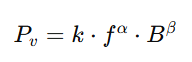
where:
- PvPv: power loss density (mW/cm³ or W/kg, depending on normalization)
- ff: frequency (Hz or kHz, material-dependent)
- BB: peak flux density (Tesla)
- k,α,βk,α,β: material-specific Steinmetz coefficients (derived from manufacturer datasheets or hysteresis curve fitting)
For audio applications (20 Hz–20 kHz), designers typically operate at low flux densities (0.3–0.8 T) to minimize distortion, far below power transformer levels. Grain-oriented silicon steel (common in EI cores) exhibits low hysteresis at audio frequencies, but eddy-current losses increase with lamination thickness.
Practical calculation steps for an EI-core audio transformer:
- Determine required primary inductance LpLp from lowest frequency (e.g., 20 Hz) and source impedance.
- Calculate turns per volt:
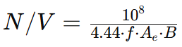 (A_e = effective core cross-section in cm²).
 - Select B_max to keep hysteresis low (commonly <0.5 T at 20 Hz for high-nickel or M6-grade steel).
- Obtain Steinmetz parameters for the core material (e.g., for typical 0.35 mm silicon steel: α ≈ 1.5–2.0, β ≈ 1.6–2.0, k adjusted accordingly).
- Compute total core loss: Pcore=Pv⋅VcorePcore=Pv⋅Vcore (V_core = core volume).
In audio designs, total core loss is often kept below 50–100 mW to avoid thermal effects and audible artifacts. Improved Generalized Steinmetz Equation (iGSE) variants better handle non-sinusoidal drive in modern hybrid systems.
Influence of Winding Techniques on Sound Quality
The winding process profoundly affects parasitic elements that shape frequency response, phase linearity, and harmonic behavior:
- Layer winding vs. sectional/interleaved winding — Interleaving primary and secondary reduces leakage inductance, extending high-frequency response (>40 kHz) and minimizing phase shift, critical for transparent line transformers.
- Bifilar or twisted-pair winding — Lowers inter-winding capacitance, improving transient response and reducing ringing.
- Wire gauge and insulation — Thicker wire reduces DC resistance (improving damping), while precision layer insulation prevents self-resonance peaks that color highs.
- Winding tension and impregnation — Inconsistent tension causes microphonic effects; vacuum impregnation with epoxy or varnish damps mechanical resonances, preserving micro-dynamics.
Poor winding increases leakage inductance (roll-off at extremes) or capacitance (resonant peaks), degrading clarity. Premium custom EI transformers employ orthogonal winding, progressive layering, and high-permeability shielding to achieve flat response from 10 Hz to 80 kHz with <0.1% THD at +24 dBu.
Custom EI Transformers as Neutrik Alternatives (1:3, 1:10 Ratios)
For microphone input (1:10 step-up) or line output (1:3), many studios seek cost-effective, high-performance alternatives to discontinued or expensive Neutrik units. Custom EI-core transformers using 50% nickel or 80% nickel alloys offer comparable (or superior) bandwidth, lower distortion at low levels, and better saturation characteristics.
Key advantages of custom EI designs:
- Tailored turns ratio and impedance (e.g., 150:15k for 1:10 mic input)
- Optimized lamination stack for minimal micro-detail compression
- Lower cost at medium volumes compared to legacy broadcast-grade stock
Professional audio manufacturers and HiFi brands increasingly specify custom EI transformers for new builds or upgrades, balancing classic tone with modern consistency.
Organizations requiring custom EI-core audio transformers—whether for 1:3 line-level isolation, 1:10 microphone step-up, or specialized ratios—are encouraged to provide detailed specifications for feasibility assessment and rapid prototyping.
Contact for custom inquiries or detailed loss modeling.